
ESX600 Exercise Bike FAQ
Assembly video
Troubleshooting & Quick Fixes
Display does not show values such as speed, distance and calories.
Repair instructions for replacing the sensor
You can find the repair video at the end of this article, after the step-by-step instructions.
Safety notice
Disconnect the device from the power supply for at least one minute before beginning maintenance.
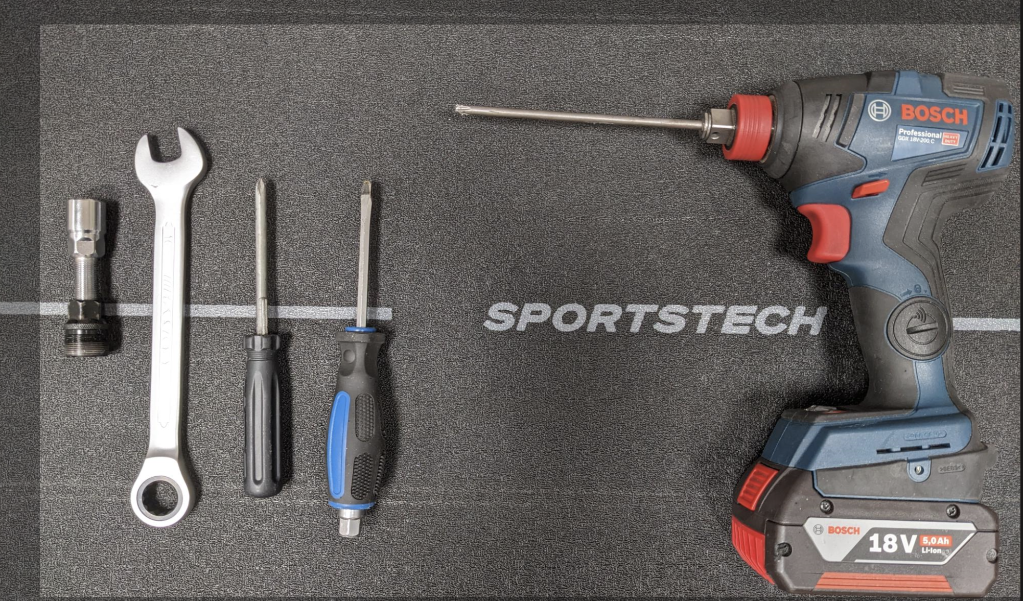
Tools required
- Crank arm puller (crank puller)
- Open-ended wrench (16 mm)
- Flat-head screwdriver
- Phillips screwdriver
- Cordless screwdriver with Phillips bit
See photo:
Step-by-step instructions
- Remove the cap:
Carefully pry off the cap with a flat-head screwdriver. - Loosen the crank nut:
Use the crank puller with the appropriate socket size to loosen the crank nut. - Remove the crank arm:
Use the other side of the crank puller to pull the crank arm off the shaft. This may require a lot of force. - Remove the rear LED cover:
Carefully pull off the push-fit LED cover. Use a flat-head screwdriver if necessary. - Loosen the screws on the side cover:
Remove all the screws securing the side cover. - Loosen the front cover:
If it is difficult to access the remaining screws, pry off the front cover with a flat-head screwdriver. - Remove the side cover:
Remove the side cover and set it aside. - Repeat on the other side:
Repeat the steps on the other side and then disconnect the plug connections to the LED strip. - Check the sensor:
If there is no sensor signal, the sensor may be defective or the magnet may be missing (which is rare). Replace the sensor:
- Loosen the screw on the sensor.
- Follow the cable and disconnect the plug connections in the lower section.
- Install the new part in reverse order.
- Reinstall the covers:
Put the cover back together. - Connect the LED plugs:
Carefully connect the LED plugs. - Install the crank arm:
Reinstall the crank arm on the right-hand side using the crank puller. Don’t forget the cap nut. - Connect the power supply cable:
Reconnect the power supply cable. - Join the left and right covers:
Align the connectors on the left and right covers and fit them together. - Secure the front screw:
Secure the screw before fitting the front cover. - Install the crank arm for the final time:
Fit the crank arm back onto the shaft. - Attach the LED cover:
Click the LED cover back into place.
That’s it!
You can find the video for the instructions here:
The spare parts list shows all the individual parts installed, from assembly through to use.
You can find all the important information in the manual.